 Introduction:

The date and time resources for the ESP32 display are requested from the NTP server via WIFI. In this project, we are using time.h library to use its method in order to request the resources from the server. At the same time, we also use the Wifi Library to connect to the wifi to establish a connection.
** The code and resources for this project can be found at this GitHub link.

Outline:
Building library to work with Heltec E-ink paper:
SPI connection:
Example library for Demo Displaying:
Bitmapping Header Library:
Connecting to the WiFi and NTP server:
ESP32 Deep Sleep Mode:
Casing and Power supply:
Result:
References:
Building library to work with Heltec E-ink paper:
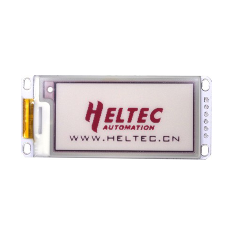
Working with Heltec E-ink displays we need to get the datasheet and library from the official site. This project is using Heltec E-ink 2.13 inc WBR display version 2 from Taobao. The device uses SPI communication, and control commands provided in the module datasheet.
SPI connection:
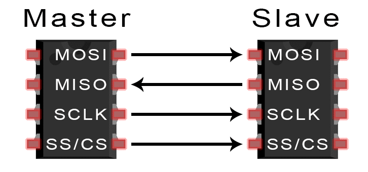
The SPI is a serial communication protocol that transfers and receives data between the master device (microcontroller) and multiple slave devices (including other microcontrollers). However, Heltec E Ink only provides one-way communication from master to slave. Of course, the actual coding will be carried out by the Arduino library SPI.h.
For the SPI connection from ESP32 to the E Ink device, we will use the following connection as references.


Example library for Demo Displaying:
From the library provided, there is an example sketch for the E ink 2.13 display.
In this example file, they provided a description of parts that support and some
code that runs with the E ink command.
The two header files that were included in the sketch are also provided by Heltac. The first one (QYEG0213RWS800_BWR.h) being the header containing different methods to operate the e ink. The second one (picture.h) contains the image in bitmap format which we will discuss later. Even though it is provided, we will modify the first header file and create our own image file.

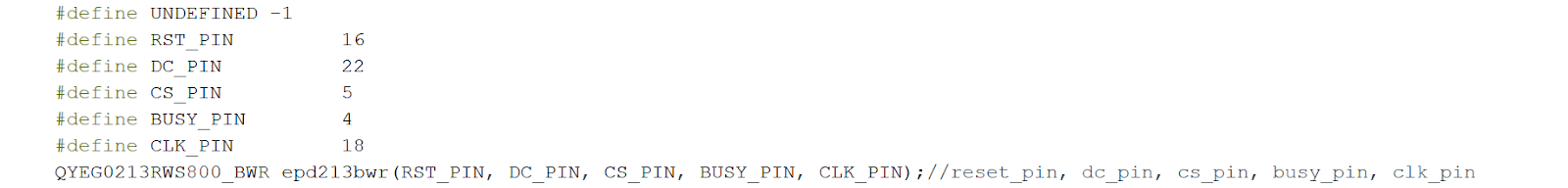
After importing the header file, we define the pin number just like the one used in the example. However, we only define the pin identity once and follow the ESP32 connection as defined above, and initialize the properties as “epd213bwr”.
We see several methods that are being used in the example:
We are going to need to initialize the E Ink display using the method and implement some of the methods including displaying all white, image display, partial image display, and updates. Moreover, we also modify the image display function so that it will take the red image and black image separately. Furthermore, we are going to remove all the updates function at the end of all methods in the .cpp file. We are removing the updates function so that we don’t refresh the display every time we call a function.
Overall our modified function should look like this:
The modified .cpp file is here.
Bitmapping Header Library:
For storing the background image and numerical digit to the E Ink, we specifically made a header containing all the necessary resources for the Elink to display the image. Before working with bitmap, first, we have to understand the inner working of this image storing method. Check out this help full link CS Principles: Unit 1 Day 5: Bitmaps encoding and decoding
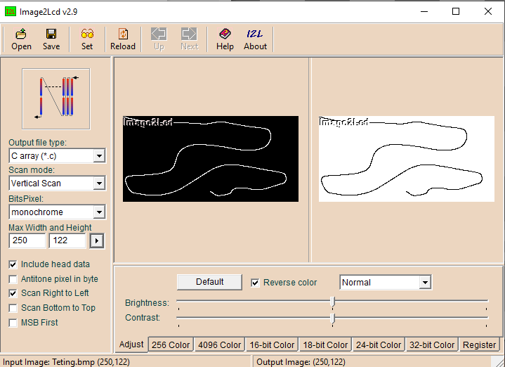
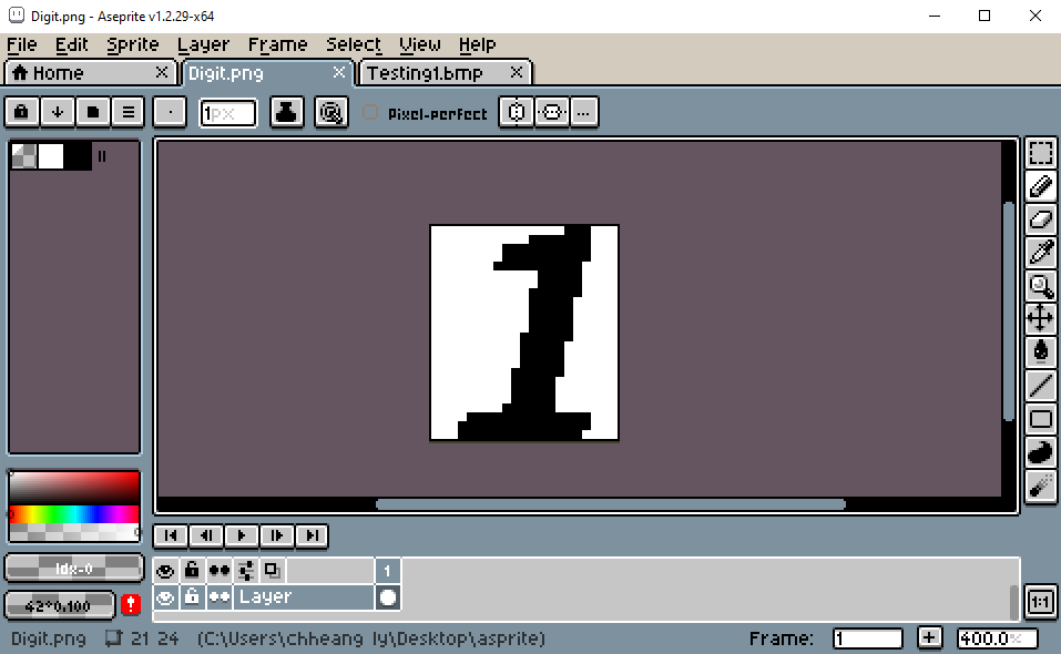
Generally, we need to resize our image so that the height is a number that is divisible by 8. In this project, I used ASprit, a pixel art tool, to create the background images 250 by 122 pixels, the numerical digits are 21 by 24 pixels. The images then save as .bmp format the loaded to Image2lcd program and convert to a c array. Finally, the C array is copied to a header file inside the project directory. The array should be 4000 in size for a full image.

Using the EPD_Dis_Part(), we can place digits and update them without changing the entire display. The first two arguments are the x and y coordinate starting from the upper left corner. The next argument is the black or red image, and after that is the size of the image, followed by the color of the image(MONO or RED). All the coordinates are planned and got from our pants or ASprite.
In the project, I created a static element (the background image) and a dynamic element (the months, days, and years digits) as different c arrays. The static element only applies to the display only once at the very beginning of the program. On the other hand, the dynamic element will refresh every time the ESP32 reawakens. This is controlled by a counter stored in the RTC of ESP32.


Connecting to the WiFi and NTP server:
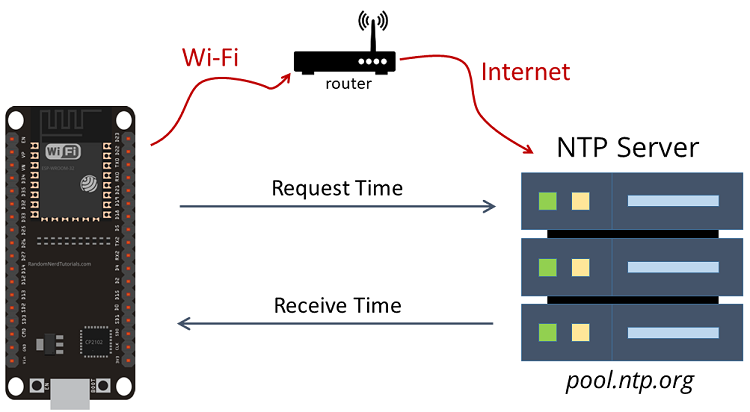
This build-in library of the ESP32 time.h is a handy library that will calculate and output the time from the NTP server. From the package, we must include the time.h and WiFi.h library to our sketch in order to use its functions. The code that we follow in this project can be found in this link.
We called the WIFI function with the SSID and Password as the parameter. Usually, it is called in a while loop, but it will not be necessary for our project. Moreover, the wifi function is called every time the ESP32 reawakens. From the time.h library, we can use the configTime function to call for Time from the NTP server. In the calling function, we need to specify the Time zone configuration and NTP server address.
However, we can only use those time data from the time structure. As a result, we needed a structure called myTime. From this structure, we can call for its attributes such as .min and .sec.
The only problem that I face using this method is inaccuracy over time. About 20s were lost in a few hours, even though the data was from the NTP server. I have been studying the problem but couldn't find the source of the problem. As such, I could only add 22s to every hour as compensation.
if(count !=0) k += 22*count;
ESP32 Deep Sleep Mode:
As part of the power saving element, the Deep Sleep mode will put the ESP32 power consumption to its lowest. The code here is based on an Example code here. To put the ESP32 to its deep sleep mode, we use the esp_sleep_enable_timer_wakeup() function to put it in that mode for a specified duration. In this project, we will put it in deep sleep mode for 1 hour, then it will restart and update the display to the current date and time.
Usually, the deep sleep mode functions are called at the end of the setup functions. So every code after the deep sleep start will not execute. Which is the reason why we will put our entire code in the setup function before the deep sleep starts.
When the ESP32 deep sleep mode starts, the variables that were not declared to the RTC section will be lost. Therefore, some necessary variables like COUNT will be declared to the RTC.
RTC_DATA_ATTR unsigned int count = 0; // RTC count
Casing and Power supply:
To power the project, we are using a 9v battery and it is connected to the ESP32 via Vin and GND pin. Even Though the size is very unsuited for this project, the voltage is in the working range for it. The problem with Chinese copied ESP32 is the power inconsistency that it only works 8v above as tested with a bench power supply. If the voltage were to drop too slow, the ESP32 will cause a BrownOut trigger and restart the MCU when it turns on the WIFI.
The casing will include the ESP32 and E Ink display and the battery. The design process used Fusion 36 and Cura. The case is designed to snap-fit with the cover to its body; plus, another section for battery storage. The 3D model for Fusion 360 is here.
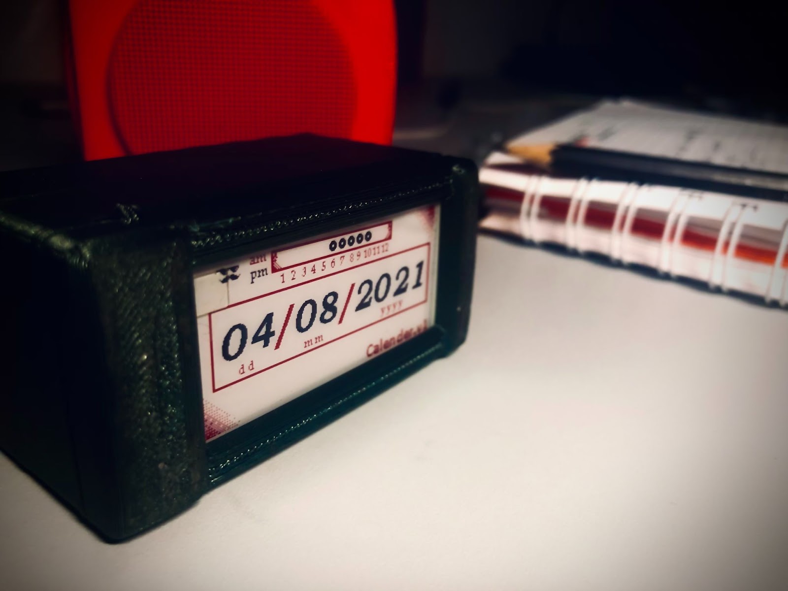
Result:
After the soldering and assembling of the parts, the device did not show any issues. Some bugs still persisted such as the incorrect time data from the NTP server, but it did not pose any major issue as we already compensate over time. Of course, the compensation method needs to be addressed in future updates.
The project consumed 100mA during run time and assumed 0A for sleep mode. Overall it should last for 10 min using a 9v battery at 650mAh capacity. However, further testing showed that it could only operate for 2 days at most. If runtime duration is a key part of the project, then we should consider solving the brownout trigger or incorporating a higher-capacity battery.

References:
Project Github Page: https://github.com/ChheangL/ChheangL/tree/NTP-Eink-Display
Heltec Offical Site: https://heltec.org/project/213-e-ink/
Library Github Page: https://github.com/HelTecAutomation/e-ink
DisplayDatasheet:https://resource.heltec.cn/download/e-ink/213/2.13b%26w%26r/QYEG0213RWS800/QYEG0213RWS800F13_V1.2.pdf
Decoding bitmap: https://www.youtube.com/watch?v=--qVCwHS6Ts
Image2LCD:http://pmoc98298.pic37.websiteonline.cn/upload/image2lcd.rar
NTP server Example: https://lastminuteengineers.com/esp32-ntp-server-date-time-tutorial/
Deep Sleep Example: https://lastminuteengineers.com/esp32-deep-sleep-wakeup-sources/
Youtube Demo: https://youtu.be/Al3E9O9QuYs


