
Theory:
The Microstrip patch antenna is a single-layer design which consists generally of four parts (Patch, ground plane, substrate, and feeding part). To analyze and design the path antenna there are many methods that could do that. The most popular are transmission lines which we assume that the patch is a transmission line or a part of a transmission line.
The transmission line method is the easiest way to study the microstrip antenna. The model represents the microstrip patch antenna by two slots, separated by a low-impedance transmission line of length L.
There are two cases to study the theory of microstrip transmission line:
which mean the width of the microstrip is smaller than the height of the substrate
and which is a wider transmission line.
We will consider our case to be the second case.
The most important thing to be considered is the maximum transfer of power (matching of the feed line with the input impedance of the antenna).
Type of feeding technique:
Edge-fed Patch
Probe-fed Patch
Inset-fed Patch
Proximity coupling
Aperture coupling
For simplicity, we will design the Edge-fed technique to feed the signal to the patch antenna.
Patch Dimension:


We can assume that the thickness of the conductor has no effect on our calculations. We can calculate the width of the microstrip line with the equation:
We will assume that the two media are equivalent to a single medium with a specific dielectric that we can call effective dielectric constant . This helps the study of the propagation field from two different media to the homogeneous medium. We can calculate the Effective Dielectric Constant:

The width of the patch must be less than the wavelength in the dielectric substrate material () so that higher-order modes will not be excited.

The fringing field makes the electric length a little bit longer than the physical length. Mathematically, the fringing length—let’s refer to it as
The length of the patch antenna is:
Length of the ground plane should be at least one wavelength. If the length of the patch is half wavelength, so the ground plane will extend to quarter wavelength to become one wavelength.
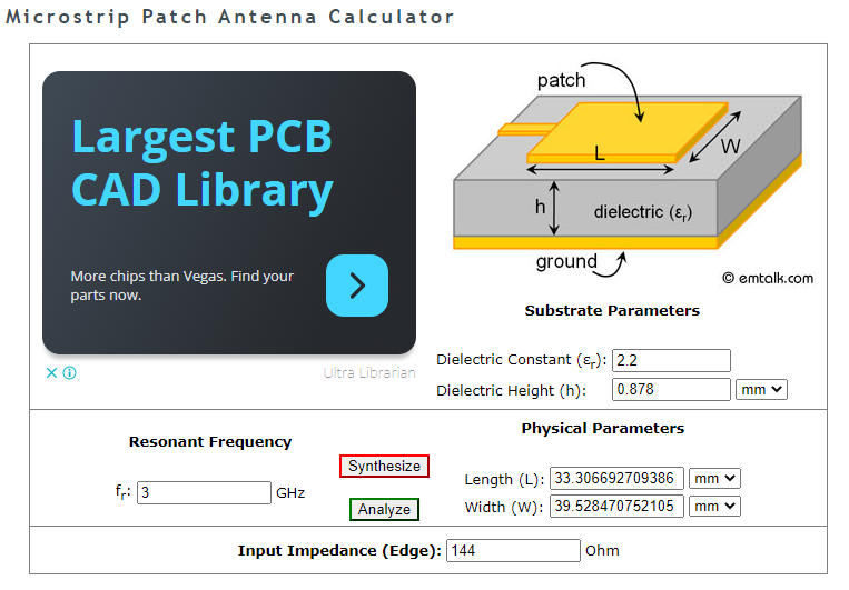
We also confirm the calculation with the online calculator:
Transition feeding:
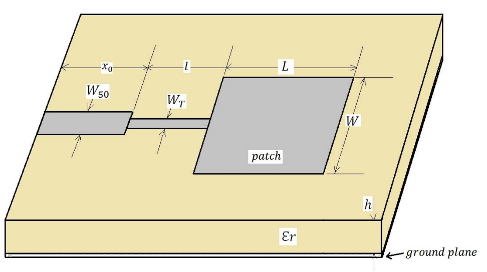
The edge Impedance of the patch antenna is given by :
The characteristic impedance of the transition section should be:
The width of the transition line is calculated from:
The width of the 50 ohm microstrip is:
The length of transition line is a quarter the wavelength:
The length of transmission line:
Design Calculation:
With the equation from the above section we can calculate both the patch antenna and its feeding microstrip line by building a python code.
Given the dielectric constant (2.2) and height of the microstrip line (0.878mm) at the frequency (3GHz)
Patch Antenna Dimension length and width:
Transmission line length and width:
Where need to calculate with the
50 ohm transmission line length and width:
For the width of the 50 ohm transmission line, it is very difficult to calculate even with python code. As such we will approximate and assume the value to be close to 3mm. The length is .
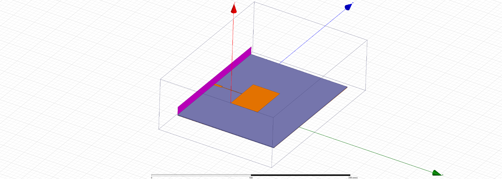
Modeling Antenna with HFSS

From the calculation, we can build the patch antenna in HFSS with the calculated parameter. However, the return loss of the antenna was not set to the right frequency (2.92GHz). We also adjusted the value of the 50 ohm transmission line to various numbers, however, it is proven to be worsen.
Tuning Parameter
Since the initial calculation provides an approximate value to the design. We need to tune the parameter and see how it will affect the Bandwidth, Resonant Frequency and Gain of the antenna. There are several methods that we can use to determine the tuning required including using S11 return plot and using the Smith chart. We are going to use the smite chart to determine how each parameter effect the overall performance:
L : Length of the patch section
W : Width of the patch section
L_t : Length of transition line
W_t : width of transition line
When tuning the parameter, we notice that the shape of the curve and the marker on the smith chart change accordingly:
When L decrease, the circle move to the right and become bigger
When L_t decreases, the curve moves to the right.
When W decreases, the circle gets bigger.
When W_t decreases, the circle gets bigger.
The smith chart below shows the effect of the W parameter. As we increase the value, the circle becomes smaller.
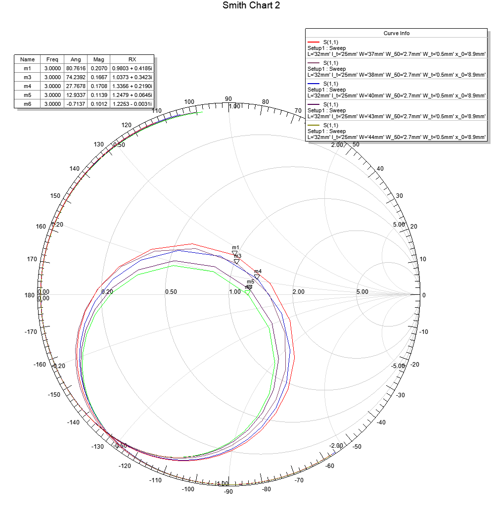
After tuning the parameter, we settle with the parameter values as shown in table 1.
The smith chart below shows the curves before and after tunning with the marker at 3GHz. After the parameters are tuned, we can see that the marker (M1) move closer to 50 ohm impedance.
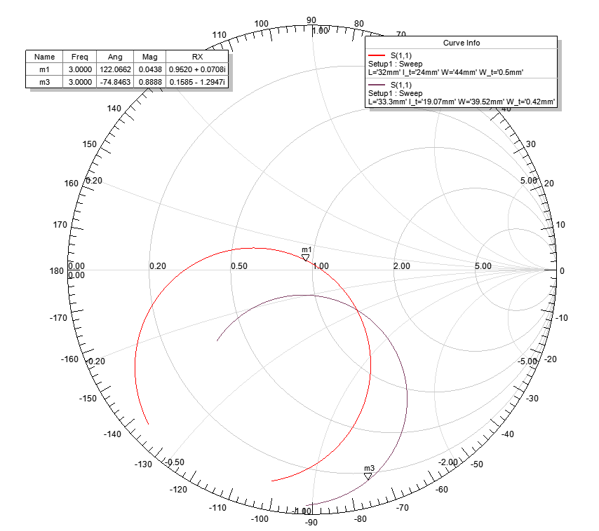
Figure below shows the Return loss before tunning (Blue) and Return loss after tunning (Red).
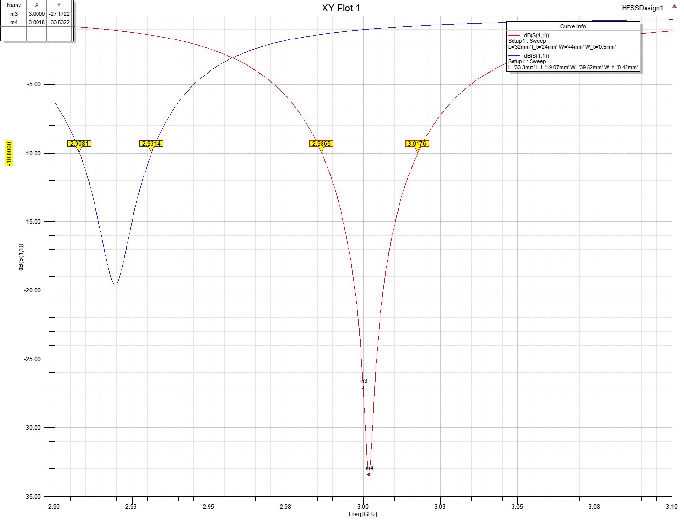
Figure below shows the 3D and 2D radiation pattern including far field at 8.36dB


Conclusion
With the approximated calculation we were still very close to the desired frequency (3.00GHz). After tunning the parameter however, the return loss, bandwidth and gain also improved. Return loss at -27dB, far field gain 8.36dB and bandwidth 31.1MHz. The bandwidth from this design is still not very good, but we can improve the bandwidth by changing the shape of the patch antenna.

References
[1] HFSS Microstrip Patch Antenna Tutorial 1 : em: talk - HFSS Tutorial 1: Microstrip Patch Antenna (emtalk.com)
[2] Microstrip Patch Antenna Model : Microstrip Patch Antenna: From Simulation to Realization (emtalk.com)
[3] Microstrip Patch Antenna Calculator : em: talk - Microstrip Patch Antenna Calculator (emtalk.com)
[4] MohammadAlhassoun, Patch Antenna : PatchAntennas.pdf (cpb-us-w2.wpmucdn.com)
[5] Ahmed Fatthi Alsager, Design and Analysis of Microstrip Patch Antenna : Microsoft Word - Microstrip antennas report.docx (diva-portal.org)
[6] EMViso, “The Rectangular Patch Antenna - Lesson 5” : https://youtu.be/wP3APBnrT9o


