Date: 2023/07/20
Reported by: Ly Chheang
Introduction

Design an interface system for the onsite alarm system to send an alert to site managers and security teams.
Our method will detect two possible scenarios:
1 - ⚠️ Alarm status (DC state)
2 - 📢 System Status (AC state)
We transfer the states to the remote MSSQL Database using VIM3 board
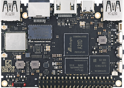
VIM3 Borad
System Overview and Challenges:
Input AC signal -> Output DC signal (under 3.3v)
Issues:
- Vim3 board GPIO pins can only support voltage up to 3.3v
- The alarm system voltage can go up to 12v DC
- The power is in AC form
Solution:
- Voltage step down using a regulator
- Convert AC to DC voltage with a signal amplifier circuit
System Diagrams:

Diagram configuration and wiring of the alarm system, sensor, sensor module (amplifier board), Vim3 board
The system is divided into two parts: the higher voltage system (before the sensor module) and the lower voltage system (VIM3). Before the signal from the alarm system board connects to the VIM3 board, multi-level system isolation between the two is designed on the sensor module board. On the included board:
- System state detector: to determine if the power to the system has failed
- Alarm state detector: to determine if the alarm system board has detected a failure or intrusion
We will discuss the design of the board in the next section
System State Detector:

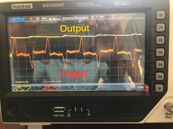
Shows the signal passing from each device from AC to DC signal
The AC state sensor uses a current transformer coupled with the AC line to detect whether power is available to the system. We can offset the AC signal from a negative value by using a simple trick with the amplifier, connecting the negative terminal to half of the input power through a voltage divider, as shown below. The capacitance C1 acts as a high-pass filter. Once the signal is purely positive, we use a voltage regulator to establish a stable DC signal.

Alarm State Detector:

To maintain low voltage into the VIM3 GPIO, we regulate the 12V from the alarm system using a 2.5V regulator. This simple method achieves signal detection when there is an alarm.
Final Design:

The module with the detection circuit and amplifier are built together using Proteus. To enable short circuit protection and easy mounting, we also printed a mounting plate for the sensor module and VIM3 board.
Tests were completed, and the application was verified. The data will be available soon.


